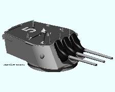
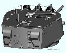
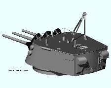
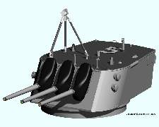
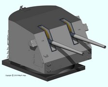
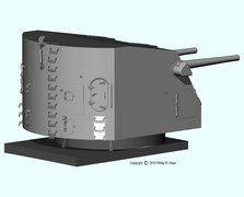
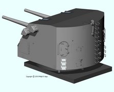
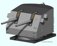
First a word about naval guns. Designations like 6"/47 and 5"/38 give the bore diameter in inches and the caliber of the gun barrel. Unlike small arms, naval gun caliber is not the bore diameter, but is the length of the barrel expressed as a number of diameters. The length of a 6"/47 gun barrel is 6 inches x 47 = 282 inches (23.5 feet). The US Navy measures from the breech block end of the barrel to the opposite end of the barrel. Some nations measure from a different position in the breech mechanism.
Another interesting fact about naval guns is that the barrels wear out fairly quickly and have to be replaced. The breech end of the barrel has "interrupted" (bayonet style) threads. It is inserted into the breech block and rotated a quarter turn to screw it in place. Removal of the guns is a fairly quick and easy process of just unscrewing the barrel a quarter turn and lifting it away with a crane.
Triple 6"/47 Gun Turret
The National Archives microfilm contained detailed blueprints for the triple 6"/47 turret, but I have found no detailed drawings of the Mk 16 guns. The gun dimensions were taken from photographs. The turret had "bloomers" (gun bags) around the barrels to keep water out of the turret. These were made of heavy rubber coated canvas that could flex when the guns were elevated and during gun recoil. The bloomer was clamped around the gun barrel and fastened to the gun port "buckler" frame on the face of the turret.
Most of the original Cleveland class turrets had an optical range finder with massive cast housings attached to the sides of the turret. However, the #4 6" turret did not have these rangefinders to reduce topside weight. The rangefinders were removed from the forward turret on a few ships during WWII to further reduce topside weight. They were removed from all turrets on the CLG conversion ships. A heavy metal plate was welded over the holes at the top rear sides of the turret.
Gun houses constructed of armor plates were called turrets. The front of the turret was 6 1/2" thick armor plate. The front curved side pieces were 3" thick and the rear side pieces were 1 1/2" thick. The rear was 1 1/4" thick armor plate with a 1 1/4" thick door mounted in a portable (removable) plate that fit into a cutout in the rear plate. The top was 3" thick and the bottom plate (floor) of the turret was 1" thick. The individual pieces of armor plate fit together with elaborate joints and were initially held together with bolts and rivets. After the plates were welded together the bolt heads were removed and the bolts were welded to the plates. The turret rode on a support bearing system attached to the inside of the barbette. The barbette was a cylindrical assembly of 6" thick armor plates extending down to the 2" armored deck (3rd deck) over the magazines.
The 6"/47 guns were capable of elevation to 60 degrees, but the original triple turret design allowed elevation only to 41 degrees. There was some discussion during the design of the Cleveland class ships of modifying the turrets to allow 60 degree elevation, so the 6 inch battery could be used for anti-aircraft fire. However, the guns could be loaded automatically only at elevations of 20 degrees or less, and this resulted in a slow rate of fire at higher elevations. This combined with a relatively slow training rate for the turret gave the guns very poor antiaircraft capability, so the original 41 degree elevation turret design was used. The turrets were later modified to allow 60 degree elevation in the Fargo class light cruisers.
The gun used "semi-fixed" ammunition with separate projectiles and powder cases. Projectiles were stored on platforms inside the barbette below the turret. Three projectile hoists raised the projectiles into the turret. Powder was contained in brass cases which were stowed in protective cans in the magazines just above the ship's keel. Three powder hoists brought powder up through the center of the barbette to each gun. Spent powder cases were ejected automatically through ports at the rear of the turret.
A tripod for highline transfers was mounted on top of the turret. It was normally stowed in the lowered position, but was raised for underway replenishment. A cable from the transferring ship passed over the top of the tripod and then down to a pad at the opposite side of the ship where it was fastened. The cable rested against the half-cylinder welded to the turret at the upper edge of the turret side. The tripod could be rigged for replenishment from either the starboard or port side.
Dual 5"/38 Gun Mount
I found a few dimensioned drawings for the twin 5"/38 gun mount, but again, no drawings for the Mk 12 guns. There are several varieties of this type gun mount but I think the type on the Okie Boat was a Mk 32 mount with a Mk 31 shield (gun house).
The gun house shield was 3/4" thick - sufficient to stop a small caliber bullet from aircraft strafing or shrapnel from near misses, but it provided no protection from naval guns or aircraft bombs. Because it was lightly armored it was referred to as a gun mount and not a turret. A hatch at the top rear allowed the mount captain to observe fire directly. A blast shield was placed around the mount captains position originally, but this was removed in later years. At different times in the ship's career various types of antennas were placed on the top of the gun mount, although at times it carried no antenna.
The gun mount rested on a heavy stand that was enclosed by a lightly armored barbette. Below this was a handling room where ready service ammunition was stowed. The 5"/38 used semi-fixed ammunition consisting of separate projectiles and powder cases. Ammunition was stored in magazines in the lower levels of the ship. Projectile and powder hoists raised the ammunition to the handling room. From there ammunition was raised into the gun house in hoists that rotated with the mount.
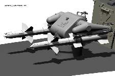
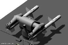
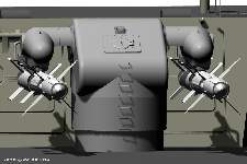
Talos Missile Launcher
The Mk 7 missile launcher was a challenge. I have been unable to obtain the blueprints so I had to work from sketches in GMM training manuals and photos. I visited the USS Little Rock and made some measurements so the overall dimensions are more or less correct.
Missiles were loaded onto the launcher through blast doors in the aft end of the missile house. The missiles traveled on rails from inside the missile house onto the launcher. The upper blast doors carried a rail section that swung up into place between the rails inside the missile house and the rails on the launcher.
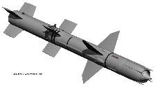
Talos Missile
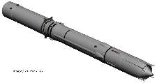
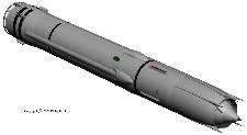
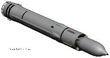
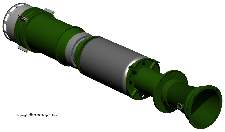
This sequence of pictures shows the Talos missile in various stages of disassembly. First is the missile ready for launch with wings and fins installed. Next is the bird without wings and fins, with missile and booster mated, in the flight ready condition as they were stowed in the Ready Service Magazine. Then we see the missile alone in the state it was when it was being tested in the TATTE cells. On the right is the missile with the cowling removed showing the warhead.
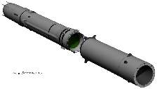
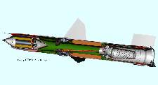
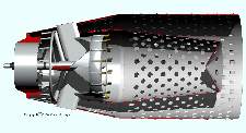
Here you see the missile with the "skins" removed showing the fuel tank in the middle and the fuel injector support ring just aft of the tank. In the section just forward of the tank were the air turbines and hydraulic motors to move the wings, and forward of that were the electronics modules of the guidance, homing and firing systems. The second picture is of an unmated missile and booster, as they were stowed in the Missile Magazine. The third picture is a cutaway showing the hollow ramjet tube with the warhead ogive at the front, the engine or "burner", and the nozzle at the end of the tail pipe. The right hand picture is a closeup of the ramjet engine.
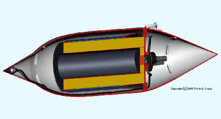
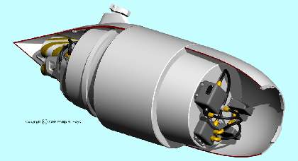
The Talos missile could carry two warheads. The Mk 46 conventional warhead is shown on the left, and the Mk 30 nuclear warhead is shown at right.

